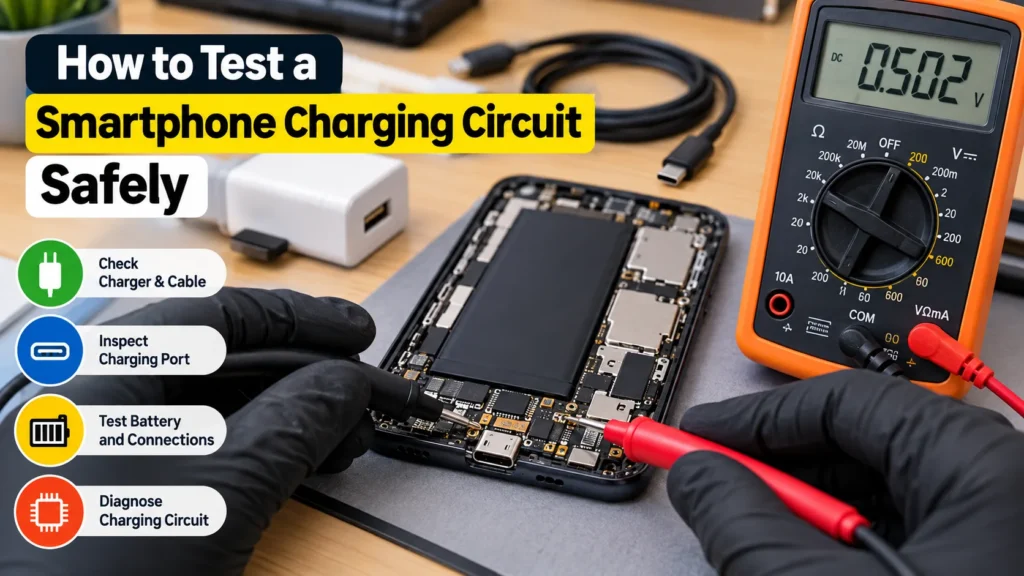
A smartphone that refuses to charge does not automatically have a faulty charging IC. A damaged cable, worn charging port, failed battery, contamination, broken connector, or board-level fault can produce similar symptoms.
The safest approach is to diagnose the charging path progressively: start with external checks, then move to connector and electrical testing only when you have the correct tools and model-specific information.
This guide explains a practical method for testing a smartphone charging circuit while reducing the risk of short circuits, component damage, battery damage, or accidental injury.
Symptoms of a Charging-Circuit Problem
Common charging symptoms include:
| Symptom | Possible areas to investigate |
|---|---|
| Phone does not detect charger | Cable, charger, port, connector, charging path |
| Charging connects and disconnects | Port contamination/damage, cable, connector |
| Battery percentage does not increase | Battery, charging path, software, charging control |
| Phone becomes unusually hot while charging | Battery, charging circuitry, short or damaged component |
| USB connection works but charging is poor | Port contacts, cable, charging negotiation/path |
| Phone shows charging but eventually shuts down | Battery, charging path, power-management circuitry |
| No response from known-good charger | Port, battery, board-level circuit or other power fault |
These symptoms are starting points rather than proof of a particular failed component.
1. Understand the Charging Path Before Testing
A modern smartphone charging system is more than a USB connector.
A simplified path can be represented as:
Charger → USB cable → charging port → protection/connection circuitry → charging/power-management circuitry → battery/system power
The exact architecture varies considerably between manufacturers and models.
Some phones also use USB-C power negotiation and additional communication lines. Therefore, a measurement that appears unusual on one model may be normal on another.
Important: Do not assume a particular pin, component or voltage is universal across smartphones.
2. Tools and Equipment
For basic diagnosis, you may need:
- Known-good compatible charger
- Known-good charging cable
- Magnifying glass or inspection microscope
- Flashlight
- Soft anti-static brush
- Digital multimeter
- USB power meter, where appropriate
- ESD-safe work area
- Manufacturer service documentation when performing board-level diagnosis
For advanced board work, additional equipment may be required, but the correct equipment depends on the phone and fault.
Do not start by probing the motherboard
If the phone has not been tested with a known-good charger and cable, beginning with board-level measurements can create unnecessary risk and may lead to incorrect conclusions.
3. Start With the External Charging Test
Before opening the phone, eliminate the easiest causes.
Step 1: Test the charger
Use a charger known to work correctly with another compatible device.
Do not assume that a charger is good simply because its indicator light turns on.
Step 2: Test the cable
Try a known-good cable that is appropriate for the phone.
Inspect both ends for:
- Bent contacts
- Dirt
- Corrosion
- Physical damage
- Loose connectors
Step 3: Inspect the charging port
Use good lighting.
Look for:
- Pocket lint
- Dust
- Corrosion
- Bent contacts
- Damaged plastic
- Loose or displaced connector components
Do not force metal objects into the port.
4. Clean the Port Carefully
If contamination is visible, remove it carefully using appropriate non-metallic tools and methods.
Avoid aggressively scraping contacts because the port can be damaged easily.
After cleaning, test the phone again with a known-good cable.
If charging returns to normal, the problem may have been mechanical or contamination-related rather than a failed charging IC.
Learn More Smartphone Has No Sound? How to Fix Audio Problems
5. Check the Charging Port Mechanically
Connect the cable normally and observe its fit.
A damaged port may show:
- Excessive looseness
- Intermittent charging when the cable moves
- Cable failing to seat correctly
- Visible physical damage
- Charging only in a particular cable position
Do not deliberately bend or force the connector to reproduce the fault.
If the port is physically damaged, replacing the port or its associated assembly may be more appropriate than performing board-level diagnosis.
6. Use a USB Power Meter When Appropriate
A USB power meter can help determine whether the phone is drawing power from the charger.
The measurement should be treated as a diagnostic clue rather than a definitive diagnosis.
For example:
No meaningful current draw
Possible areas include:
- Cable
- Charging port
- Connection between port and motherboard
- Charging circuitry
- Battery/system power condition
Some current draw but battery does not charge
Possible areas include:
- Battery condition
- Charging-control circuitry
- Charging restrictions
- Thermal protection
- System-level power problems
Intermittent current
Possible areas include:
- Poor connector contact
- Damaged port
- Cable problem
- Protection or charging-control behavior
The exact current expected during charging is model-dependent [VERIFY]. Do not diagnose a component solely from a single current reading.
7. Test the Charging Port With a Multimeter
A multimeter can be useful, but this is where the risk increases.
Before performing electrical measurements:
- Identify the exact phone model.
- Identify the board revision if applicable.
- Obtain reliable service documentation.
- Determine the connector pinout.
- Confirm the expected measurement conditions.
- Use the correct meter mode.
- Prevent probe tips from touching adjacent contacts.
Never guess a pinout
USB-C and other smartphone connectors can contain multiple power, ground and communication contacts.
A pin that looks like a convenient test point may not be the point you expect.
Therefore:
Do not apply voltage, resistance expectations or continuity assumptions from another phone model to the device being repaired.
8. Continuity Testing: Understand the Limitation
Continuity mode can help identify whether a physical connection exists between two known points.
However, a continuity beep does not automatically prove that a charging circuit is healthy.
For example, continuity can exist through:
- Components
- Protection devices
- Parallel paths
- Semiconductor structures
The meter’s behavior must therefore be interpreted using the circuit schematic or service documentation.
A common mistake
A technician finds continuity between two points and concludes:
“The charging circuit is good.”
That conclusion is too broad.
Continuity is only one piece of diagnostic information.
9. Resistance-to-Ground Measurements
Resistance measurements can sometimes help identify an abnormal short or suspicious power rail.
However, resistance-to-ground values are highly dependent on the specific circuit.
The correct procedure requires:
- Correct test points
- Correct meter mode
- Correct board condition
- Knowledge of the circuit
- Appropriate reference measurements
Do not use a generic resistance number from an unrelated smartphone as a pass/fail threshold.
If a model-specific value is required, use the manufacturer’s service documentation or a reliable board-level reference [VERIFY].
10. Check the Battery Before Blaming the Charging IC
The battery is an important part of the charging system.
A phone may show charging-related symptoms because of a degraded, damaged, disconnected or deeply discharged battery.
Inspect:
- Battery connector
- Battery condition
- Signs of swelling
- Corrosion
- Physical damage
- Connector seating
Stop if the battery is swollen or damaged
Do not continue ordinary charging experiments with a visibly swollen, punctured or damaged lithium-ion battery.
A damaged battery should be handled using appropriate battery-safety procedures.
11. Follow a Diagnostic Decision Tree
A simple diagnostic sequence can prevent unnecessary component replacement.
Phone does not charge
        │
        ▼
Test known-good charger + cable
        │
   ┌────┴────┐
   │         │
Works      Still fails
   │         │
   ▼         ▼
Inspect     Inspect charging port
normal      │
            ▼
       Clean/test port
            │
       ┌────┴────┐
       │         │
     Works     Fails
       │         │
       ▼         ▼
    Finish   Check battery
                 │
                 ▼
        Check connector/path
                 │
                 ▼
       Board-level diagnosis
       using model documentation
This sequence is safer than immediately replacing a charging IC.
12. Board-Level Charging Diagnosis
If the basic tests fail, board-level diagnosis may be necessary.
At this stage, identify:
- Charging connector
- Battery connector
- Relevant protection components
- Charging/power-management circuitry
- Relevant power rails
- Communication or negotiation circuitry where applicable
The exact circuit depends on the device.
A board schematic or boardview, when legitimately available for the repair, can make the diagnostic process much more reliable.
Do not replace the charging IC based on symptoms alone
A phone that does not charge can have a fault elsewhere in the charging path.
Before replacing a major IC, establish evidence that the component is actually implicated.
13. Example Diagnostic Scenario
Imagine a phone that shows no charging response.
Test 1 — Known-good charger
The charger works with another device.
Result: Charger becomes less likely to be the cause.
Test 2 — Known-good cable
The replacement cable produces the same result.
Result: Cable becomes less likely.
Test 3 — Port inspection
The port contains visible contamination.
Clean it appropriately and retest.
Result: If charging returns, board-level repair may not be necessary.
Test 4 — Port inspection is normal
The phone still does not charge.
Now inspect the port mechanically and, where appropriate, investigate the charging path.
Test 5 — Battery and board diagnosis
If external and mechanical checks do not identify the fault, further electrical diagnosis may be appropriate.
This prevents a common repair mistake: replacing expensive board components before eliminating simple causes.
14. Common Mistakes During Charging-Circuit Testing
Using another phone’s measurements
Different models can use different charging architectures.
Better approach: Use model-specific documentation.
Probing powered circuits carelessly
A slipping probe can bridge adjacent contacts and cause a short.
Better approach: Use appropriate probes and stable positioning.
Measuring resistance on an energized circuit
Resistance mode is not intended for measuring an actively powered circuit.
Better approach: Follow the meter manufacturer’s instructions and ensure the circuit is in the correct condition before resistance testing.
Assuming a charging IC is faulty
A charging symptom does not identify a specific failed component.
Better approach: Work from the charger toward the battery and board circuitry.
Continuing after detecting battery damage
A swollen or physically damaged battery should not be treated as an ordinary charging fault.
Better approach: Stop and follow appropriate lithium-battery safety procedures.
15. When to Stop DIY Testing
Professional repair or model-specific service documentation is appropriate when:
- The battery is swollen or damaged.
- The motherboard has liquid damage.
- The charging connector has broken solder joints.
- The phone becomes abnormally hot.
- There is evidence of a short circuit.
- Board-level components need removal.
- You do not have the correct schematic or test information.
- The required measurement could damage the device if performed incorrectly.
For board-level work, manufacturer or appropriate model-specific service documentation should take priority over generic internet measurements.
16. Safe Testing Checklist
Before testing:
- Confirm the exact phone model.
- Test a known-good charger.
- Test a known-good cable.
- Inspect the charging port.
- Check for contamination or physical damage.
- Check the battery for visible damage.
- Use the correct meter mode.
- Confirm the connector pinout.
- Use model-specific documentation for electrical measurements.
- Avoid accidental probe-to-probe or pin-to-pin shorts.
- Stop if the battery is swollen, damaged or overheating.
Technical Safety Note
Smartphone charging circuits and lithium-ion batteries can present electrical, thermal and fire hazards if incorrectly tested or damaged.
Phone models, motherboard revisions and charging architectures differ. Do not assume voltage, resistance, pinout or component values from another model are applicable to your phone. For board-level diagnosis, use appropriate model-specific service documentation and professional repair procedures.
Frequently Asked Questions
Can a multimeter test whether a phone charging circuit is working?
A multimeter can provide useful electrical measurements, but it cannot determine the complete health of a charging circuit from one measurement. The reading must be interpreted according to the device’s circuit and test conditions.
Can a bad charging port cause the phone not to charge?
Yes. A damaged, contaminated or poorly connected charging port can prevent reliable electrical contact and cause charging problems.
Should I replace the charging IC if the phone does not charge?
Not automatically. The charger, cable, port, battery, connector and other parts of the charging path should be considered before replacing a major board component.
Can I use resistance mode while the phone is powered?
Resistance measurements should not be performed on an energized circuit unless the specific test procedure and equipment explicitly support it. Follow the meter instructions and the device-specific diagnostic procedure.
What should I test first?
Start with the charger and cable, then inspect the charging port and battery condition before progressing toward board-level diagnosis.


Join the Conversation
Have a question or insight to share? Add your thoughts below.